
Wireless Local Area Networks (WLANs) have become an essential part of our lives, providing internet access and connectivity to our devices. Designing and implementing an effective WLAN architecture requires careful consideration of various factors. Here’s a breakdown of key elements involved in WLAN network architecture and design:
Network Components:
- Access Points (APs): These act as wireless hubs, transmitting and receiving Wi-Fi signals. Strategically placed APs ensure adequate coverage throughout the desired area.
- Wireless Clients: These are the devices that connect to the Wi-Fi network, such as laptops, smartphones, tablets, and smart home devices.
- Wireless Network Controllers (Optional): For large or complex networks, controllers provide centralized management, configuration, and monitoring of multiple APs.
- Wired Network Backbone: This is the wired network infrastructure (Ethernet cables, switches, routers) that connects APs and provides internet access.
Design Considerations:
- Network Requirements: Define the intended use of the network (home, office, large venue) and the number of users to determine the required capacity.
- Coverage Area: Analyze the physical layout of the space and identify potential signal obstacles like walls or furniture. Plan AP placement to ensure adequate and even signal distribution.
- Scalability: Consider future growth and choose a design that can accommodate adding more APs or clients easily.
- Security: Implement strong security measures like WPA2 encryption and access control to protect your network from unauthorized access and data breaches.
- Radio Frequency (RF) Environment: Analyze potential sources of interference like cordless phones or microwave ovens operating in the same frequency range as Wi-Fi (2.4 GHz or 5 GHz).
WLAN Standards:
- 802.11 Standards: These define the technical specifications for Wi-Fi communication, including data rates, frequencies, and security protocols. Different standards like 802.11n (Wi-Fi 4), 802.11ac (Wi-Fi 5), and 802.11ax (Wi-Fi 6) offer varying levels of performance and features.
- Client Device Compatibility: Ensure your chosen WLAN design and standards are compatible with the Wi-Fi capabilities of your client devices.
Advanced Features:
- Roaming: Allows devices to seamlessly switch between APs as users move around the network, maintaining uninterrupted connectivity.
- Load Balancing: Distributes traffic evenly across multiple APs to prevent overloading and ensure optimal performance for all connected devices.
- Mesh Networking: Utilizes a network of interconnected APs to create a blanket of Wi-Fi coverage, especially beneficial for large or complex spaces.
- Quality of Service (QoS): Prioritizes network traffic for applications like voice calls or video conferencing to ensure smooth and uninterrupted experience.
Design Tools and Resources:
- Site Surveys: Conducting a site survey helps identify potential signal obstacles and determine optimal AP placement for strong and even coverage.
- WLAN Design Software: Software tools can assist in modeling signal propagation and predicting coverage areas based on AP placement and network parameters.
- Manufacturer Guidelines: Refer to access point manufacturer’s recommendations for best practices on deployment and configuration for their specific models.
By understanding the network components, design considerations, and available features, you can create a WLAN network architecture that meets your specific needs and provides reliable, secure, and high-performing Wi-Fi connectivity for your users.
Power over Ethernet (PoE)
Power over Ethernet (PoE) is a technology that eliminates the need for separate power cables for certain network devices. It allows data and power to be transmitted over a single Ethernet cable, simplifying deployment and reducing cabling costs.
- Power Source Equipment (PSE):
The PSE is the key component in a PoE system. It’s the device that provides the electrical power that gets transmitted over the Ethernet cable. There are two main types of PSE:
- Classifying PSE (PSE-C):
- This type of PSE can detect the power requirements of a connected Powered Device (PD) before supplying power.
- It uses a classification handshake to determine the PD’s power class and then supplies the appropriate voltage and current.
- This is the most common type of PSE used in modern PoE deployments.
- Non-Classifying PSE (PSE-Non):
- This simpler type of PSE provides a fixed voltage (typically 48V) to any device connected to it.
- It doesn’t perform any classification handshake and simply supplies power.
- PSE-Non is less common today due to potential compatibility issues with some PDs.
PSE Standards:
There are two main PoE standards that define the specifications for power delivery over Ethernet cables:
- IEEE 802.3af (PoE): This is the original PoE standard, also known as PoE. It provides up to 15.4 watts of power to PDs.
- IEEE 802.3at (PoE+): This is the high-power PoE standard, also known as PoE+. It can deliver up to 30 watts of power, suitable for more demanding devices like IP cameras with pan-tilt-zoom (PTZ) functionality.
PSE Features:
- Power Levels: PSEs come in different wattages, supporting either PoE (up to 15.4W) or PoE+ (up to 30W) standards.
- Port Counting: PSEs typically have multiple Ethernet ports, allowing them to power several devices simultaneously. Some models offer advanced features like:
- Port-based Power Control: Enables enabling or disabling power on individual ports for granular control.
- Priority Levels: Allows prioritizing power delivery to critical devices in case of overload situations.
- Remote Management: Provides the ability to monitor and manage power delivery remotely for certain PoE switch models.
Key points to consider when implementing PoE:
- PSE Compatibility: Ensure your chosen PSE is compatible with the PoE standards and power requirements of your Powered Devices (PDs).
- Cable Length: PoE standards specify limitations on cable length for guaranteed power delivery. Longer cables might cause voltage drops that affect PD operation.
- PSE Power Budget: Choose a PSE with sufficient total power capacity to handle the combined power requirements of all connected PDs.
By understanding the role of Power Source Equipment (PSE) in PoE systems and considering the various standards, features, and implementation factors, you can ensure a successful deployment that simplifies network infrastructure and efficiently powers your PoE-compatible devices.
Power over Ethernet (PoE) Powered Devices (PDs)
In Power over Ethernet (PoE) systems, Powered Devices (PDs) are the network devices that receive electrical power along with data over a single Ethernet cable. This eliminates the need for separate power supplies, streamlining installation and reducing cable clutter.
Types of Powered Devices (PDs):
A wide range of network devices can leverage PoE technology. Here are some common examples:
- VoIP Phones: Voice over IP phones utilize PoE for both data and power, eliminating the need for a separate power outlet for each phone.
- Wireless Access Points (APs): PoE can power low- to medium-power access points, simplifying deployment in areas where access to power outlets might be limited.
- IP Cameras: Security and surveillance cameras with PoE can operate without nearby power outlets, offering more flexible placement options.
- PoE Lighting: LED lighting fixtures can be powered by PoE, enabling centralized control and easier integration with smart building systems.
- PoE Displays: Digital signage and kiosk displays can benefit from PoE for both data and power, reducing cabling requirements.
- Point-of-Sale (PoS) Terminals: Retail environments can leverage PoE to power PoS terminals, streamlining setup and management.
PD Capabilities:
- Power Requirements: PDs have varying power consumption levels depending on their functionality. PoE standards (802.3af/at) provide up to 15.4W (PoE) or 30W (PoE+) for PDs.
- PoE Class: Each PD falls into a specific PoE class (0-8) based on its maximum power consumption. Knowing the PoE class helps determine compatibility with PSEs (Power Source Equipment).
- PD Detection and Classification: The PD communicates with the PSE during connection to identify its power requirements. This ensures the PSE supplies the appropriate voltage and current.
Implementation Considerations:
- PD Compatibility: Verify that your chosen PDs are compatible with the PoE standards and power capabilities of your PSEs.
- Power Consumption: Consider the combined power draw of all PDs when selecting a PSE to ensure it has sufficient power capacity.
- Cable Length: PoE standards specify limitations on cable length for guaranteed power delivery. Longer cables might cause voltage drops that affect PD operation.
Benefits of PoE-Powered Devices:
- Simplified Installation: Eliminates the need for separate power outlets for PDs, reducing cabling requirements and installation time.
- Flexibility: Allows for placement of devices in areas where power outlets might be limited or unavailable.
- Centralized Power Management: PoE enables centralized control and monitoring of power delivery to PDs through compatible PSEs.
- Cost Savings: PoE can potentially reduce overall system costs by eliminating the need for separate power supplies and transformers.
Basically, Powered Devices (PDs) are the recipients of power and data in PoE deployments. Understanding the different types of PDs, their power requirements, and compatibility factors is crucial for a successful PoE implementation.
Power over Ethernet (PoE): Midspan vs Endpoint PSEs
In Power over Ethernet (PoE) systems, both midspan and endpoint PSEs (Power Source Equipment) inject electrical power along with data over an Ethernet cable to Powered Devices (PDs). However, they differ in their placement within the network and how they integrate with existing infrastructure.
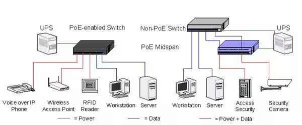
The figure above illustrates the difference between PoE enabled switch and Non-PoE switch.
Midspan PSE:
- Concept: A midspan PSE is a standalone device inserted between a non-PoE Ethernet switch and a PD. It acts as an intermediary, receiving data and power from the switch and then adding the PoE functionality before transmitting it to the PD over a single Ethernet cable.
- Applications: Ideal scenarios include:
- Adding PoE functionality to existing non-PoE network switches.
- Selective PoE deployment for specific devices on a network.
- Situations where the PoE switch model desired might not be available due to budget or features.
- Benefits:
- Offers flexibility in PoE deployment without replacing existing network switches.
- Cost-effective solution for adding PoE to a limited number of devices.
- Wide variety of midspan PSE options available to accommodate different power requirements (PoE/PoE+) and port configurations.
- Considerations:
- Requires an additional device in the network compared to endpoint PSEs.
- Might introduce an extra point of failure in the network compared to integrated PoE switches.
- Management of PoE functionality might be separate from the network switch.
Endpoint PSE:
- Concept: An endpoint PSE is an integrated component within a PoE switch. These switches have built-in PoE functionality and can supply power directly to PDs over Ethernet cables connected to designated PoE ports.
- Applications: Well-suited for scenarios where PoE is required for a significant number of devices or when centralized management of PoE functions is desired.
- Benefits:
- Offers a more streamlined solution by integrating PoE functionality within the switch itself.
- Enables centralized management and configuration of PoE settings for all connected devices through the switch interface.
- Scalable solution for powering multiple PDs with various power requirements.
- Considerations:
- Requires replacing existing non-PoE switches with PoE-capable models, potentially involving higher upfront costs.
- PoE functionality and features might be limited by the chosen PoE switch model.
Choosing Between Midspan and Endpoint PSEs:
Here’s a quick guide to help you decide:
- Limited PoE needs: Opt for a midspan PSE if you only need to power a few devices and want to avoid replacing your existing network switch.
- Extensive PoE deployment: Choose endpoint PSEs (PoE switches) for larger deployments where you’ll be powering numerous devices and require centralized PoE management.
- Budget: Midspan PSEs can be a more budget-friendly option for adding PoE to a limited number of devices. However, endpoint PSEs (PoE switches) might offer a better return on investment in the long run for extensive deployments due to scalability and management benefits.
Notes:
- Ensure compatibility between your chosen PSE (midspan or endpoint) and the PoE standards and power requirements of your PDs.
- Consider factors like scalability, manageability, and total cost of ownership when making your decision.
By understanding the distinctions between midspan and endpoint PSEs, you can select the most suitable solution for your specific PoE deployment needs.
Power over Ethernet (PoE): Power Classes and Differences Between PSE and PD
Power over Ethernet (PoE) simplifies network deployments by transmitting both data and electrical power over a single Ethernet cable. This eliminates the need for separate power supplies for compatible devices (Powered Devices – PDs). However, it’s crucial to understand the power classes and the differences between Power Source Equipment (PSE) and PDs to ensure proper functioning.
PoE Power Classes:
The IEEE 802.3 standards define PoE classes that categorize PDs based on their maximum power consumption. These classes are crucial for ensuring compatibility between PSEs and PDs. Here’s a breakdown of the most common classes:
| Class | Maximum Power (Watts) | Typical Applications |
|---|---|---|
| 0 | Up to 4.9 (Low Power) | VoIP Phones (basic) |
| 1 | Up to 3.84 (Very Low Power) | Low-power sensors |
| 2 | Up to 6.49 (Low Power) | VoIP Phones (advanced) |
| 3 (PoE+) | Up to 25.5 (High Power) | Wireless Access Points (low-power), IP Cameras (basic) |
| 4 (PoE++/Type 4) | Up to 90 (Ultra High Power) | Wireless Access Points (high-power), PTZ IP Cameras, Building Automation Devices |
PSE vs. PD Power Differences:
While both PSEs and PDs deal with power in PoE systems, they have distinct roles:
- Power Source Equipment (PSE):
- Provides power to the PD.
- Classifies the PD during connection to determine its power requirements.
- Supplies the appropriate voltage (typically 48V) and current based on the PD class.
- Key Point: PSEs can deliver a maximum wattage according to their specifications (PoE or PoE+ standards). This wattage needs to be equal to or greater than the power requirement of the PD it’s supplying.
- Powered Device (PD):
- Receives power from the PSE over the Ethernet cable.
- Indicates its power class during connection with the PSE.
- Draws power up to its maximum class rating (e.g., a Class 3 PD can draw up to 25.5 watts).
- Key Point: PDs cannot supply power; they only consume power delivered by the PSE.
Example Scenario:
- You have a PoE switch (PSE) with PoE+ (up to 30 watts) capabilities.
- You connect a VoIP phone (PD) that falls under Class 2 (up to 6.49 watts).
- During connection, the PSE will classify the PD and identify its Class 2 rating.
- The PSE will then supply the necessary voltage and current to provide up to 6.49 watts to the phone, ensuring proper operation.
Important Considerations:
- Always verify compatibility between your PSE’s maximum power output and the PD’s class rating.
- Using a PSE with insufficient wattage for a PD can lead to power shortage and device malfunction.
- Some advanced PSEs offer features like overload protection and power prioritization for critical devices.
By understanding PoE power classes and the distinctions between PSE and PD power roles, you can ensure a successful PoE deployment that meets the power requirements of your devices. Remember, proper planning and selecting compatible equipment are crucial for a reliable and efficient PoE network.
Power over Ethernet (PoE): Power Budgets and Port Density
Power over Ethernet (PoE) offers a convenient way to deliver both data and power to compatible devices using a single Ethernet cable. However, it’s essential to consider two key factors for successful PoE implementation: power budgets and powered port density.
Power Budget:
- Concept: The power budget refers to the total amount of power a PoE switch (PSE) can deliver to all its connected Powered Devices (PDs) simultaneously. It’s typically measured in watts (W).
- Importance: The power budget ensures your PoE switch has enough capacity to power all connected devices without overloading. Exceeding the power budget can lead to:
- Power shortages: Devices might not receive enough power to function properly or might experience intermittent operation.
- Switch malfunctions: In severe cases, exceeding the power budget could overload the PSE, causing the switch to malfunction or even shut down.
- Calculating Power Budget:
- Identify the maximum power consumption (wattage) of each PD you intend to connect. Refer to the PD’s specifications or PoE class.
- Add up the maximum power consumption of all the PDs you plan to connect to the switch.
- This sum represents the total power required by your PDs. Ensure this value stays below the PoE switch’s advertised power budget.
Powered Port Density:
- Concept: Powered port density refers to the number of PoE-capable ports available on a PoE switch and the total power each port can deliver. It’s often expressed as a combination (e.g., 8 ports at 30W each).
- Importance: Powered port density helps determine how many devices you can power simultaneously and the maximum power each device can receive. It’s crucial to consider:
- Number of PoE devices: Ensure the switch has enough PoE ports to accommodate all your devices.
- Individual device power needs: Verify that each PoE port provides sufficient power for the connected PD.
Example Scenario:
- You have a PoE switch with a total power budget of 250 watts and 8 PoE ports, each capable of delivering 30 watts (8 ports * 30W/port = 240W).
- You plan to connect the following PoE devices:
- 4 VoIP phones (Class 2, each consuming up to 6.49W)
- 2 IP cameras (Class 3, each consuming up to 25.5W)
- Power Consumption Calculation:
- Phones: 4 phones * 6.49W/phone = 25.96W
- Cameras: 2 cameras * 25.5W/camera = 51W
- Total PD consumption: 25.96W + 51W = 76.96W
- Power Budget Analysis:
- The total power consumption of your PDs (76.96W) is well within the switch’s power budget (250W).
- Each PoE port on the switch can deliver 30 watts, which is sufficient for the VoIP phones (Class 2) and potentially even some basic IP cameras (Class 3).
Key Points:
- Always choose a PoE switch with a power budget that exceeds the combined power requirements of all your PDs.
- Consider future expansion needs when selecting a PoE switch. Choose a model with a power budget and powered port density that can accommodate potential growth in the number of PoE devices.
- Some PoE switches offer features like overload protection that automatically shut down specific ports if the power budget is exceeded.
By understanding power budgets and powered port density, you can make informed decisions when selecting PoE switches for your network. This ensures your devices receive the necessary power for proper operation while staying within the switch’s capabilities.
Wireless LAN Architectures: Centralized vs. Distributed Data Forwarding
Wireless Local Area Networks (WLANs) rely on specific architectures to manage data traffic and ensure efficient communication between devices. Two main approaches dominate WLAN design: Centralized data forwarding and Distributed data forwarding. Understanding their differences, advantages, and constraints is crucial for choosing the optimal architecture for your network needs.
Centralized Data Forwarding:
- Concept: In a centralized architecture, a dedicated Wireless Network Controller (WLC) acts as the central brain of the network. All data traffic between wireless access points (APs) and client devices is routed through the WLC for processing and forwarding.
- Data Flow:
- Client devices send or receive data.
- The data is transmitted to the nearest access point (AP).
- The AP encapsulates the data in a tunnel and forwards it to the WLC.
- The WLC processes the data, performs tasks like security checks and routing, and determines the appropriate destination.
- The WLC forwards the data back to the intended recipient AP.
- The recipient AP then transmits the data to the client device.
- Advantages:
- Centralized Management: The WLC simplifies network administration, configuration, and security policies.
- Scalability: The architecture can scale well by adding more APs and managing them centrally through the WLC.
- Advanced Features: WLCs often offer advanced features like roaming (seamless handoff between APs), load balancing, and guest network management.
- Constraints:
- Single Point of Failure: The WLC is a critical component. If it fails, the entire network can become dysfunctional.
- Increased Latency: Data packets travel a longer path due to the additional hop through the WLC, potentially increasing latency (delay).
- Cost: Implementing a centralized architecture requires purchasing and maintaining the WLC, adding to the initial cost.
Distributed Data Forwarding:
- Concept: In a distributed architecture, there’s no central controller. Access points (APs) are more intelligent and handle data forwarding independently. They communicate directly with each other and with client devices, making forwarding decisions locally.
- Data Flow:
- Client devices send or receive data.
- The data is transmitted to the nearest access point (AP).
- The AP performs security checks, routing decisions, and forwards the data directly to the intended recipient AP (or client device if within range).
- The recipient AP then transmits the data to the client device.
- Advantages:
- Reduced Latency: Data packets take a more direct path, potentially resulting in lower latency compared to a centralized architecture.
- Increased Reliability: The network’s functionality isn’t dependent on a single point of failure (WLC).
- Lower Cost: No separate WLC is needed, potentially reducing initial setup costs.
- Constraints:
- Complexity: Managing and configuring individual APs can be more complex compared to a centralized approach.
- Limited Scalability: Adding a large number of APs in a distributed network might require additional configuration and management overhead.
- Fewer Advanced Features: Distributed APs might offer fewer advanced features compared to those managed by a central controller.
Choosing the Right Architecture:
The optimal WLAN architecture depends on your specific network requirements. Consider these factors:
- Network Size and Complexity: For larger networks with complex needs, a centralized architecture with a WLC might offer better manageability and scalability.
- Performance Requirements: If low latency is critical, a distributed architecture might be preferable.
- Budget: Centralized architectures have higher initial costs due to the WLC, while distributed architectures can be more cost-effective initially.
- Technical Expertise: Managing a centralized architecture might be easier for IT teams with experience with WLCs.
By understanding the strengths and weaknesses of both centralized and distributed data forwarding architectures, you can make an informed decision that best suits your WLAN needs.
Control, Management and Data planes
In wireless local area networks (WLANs), the control, management, and data planes represent three distinct functionalities that work together to ensure seamless wireless communication. Here’s a breakdown of each plane and its role:
1. Control Plane (CP):
- Function: The control plane acts as the brain of the WLAN, responsible for establishing and maintaining network connections. It manages the flow of control information, which includes:
- Association: Negotiating connection between client devices (like laptops or smartphones) and access points (APs).
- Authentication: Verifying the identity of users and devices attempting to access the network.
- Authorization: Granting or denying access to network resources based on user permissions.
- Security: Distributing encryption keys and managing security protocols for secure communication.
- Roaming: Facilitating seamless handoff of client devices between access points as they move around the network.
- Routing: Determining the optimal path for data packets to reach their destination.
- Components: The control plane primarily involves software components like:
- Wireless Network Controllers (WLCs) in centralized architectures.
- The control firmware running on individual access points in distributed architectures.
2. Management Plane (MP):
- Function: The management plane focuses on monitoring, configuring, and troubleshooting the WLAN. It allows network administrators to:
- Provision and configure access points: Set up AP parameters, security settings, and firmware updates.
- Monitor network performance: Track metrics like signal strength, connected devices, data throughput, and potential errors.
- Perform diagnostics: Identify and troubleshoot network issues.
- Manage user access: Create and manage user accounts, assign permissions, and enforce access policies.
- Components: The management plane primarily involves:
- Management consoles: Software tools used by network administrators to configure and monitor the WLAN.
- Web interfaces or command-line interfaces (CLIs) on access points.
3. Data Plane:
- Function: The data plane is responsible for the actual transmission and reception of user data traffic across the wireless network. It handles the forwarding of data packets between client devices and the wired network backbone.
- Components: The data plane primarily involves the hardware components responsible for data transfer:
- Wireless network adapters in client devices.
- Radio transceivers in access points.
- Ethernet ports on access points for connecting to the wired network.
Key Points:
- The control, management, and data planes work together to ensure efficient and secure wireless communication.
- The control plane dictates how data flows, while the management plane oversees network health and configuration.
- The data plane handles the actual transmission and reception of user data.
Analogy:
Think of a WLAN as a highway system. The control plane acts like the traffic control center, managing traffic flow and routing decisions. The management plane is like the highway maintenance crew, ensuring the roads are in good condition and traffic signs are clear. Finally, the data plane represents the actual vehicles traveling on the highways, carrying passengers and cargo (data).
Scalability and Availability Solutions for Wireless LANs
As your wireless network grows or your needs change, ensuring scalability and availability becomes crucial. Here are some solutions to address these challenges:
Scalability Solutions:
- Hierarchical Network Design: Implement a multi-tier architecture with access points (APs) connected to wireless controllers, which then connect to a central switch. This allows for easier management and scalability by adding more APs and controllers as needed.
- High-Density AP Deployment: Utilize a higher density of lower-powered APs to provide better coverage and capacity in areas with many users. This can be particularly beneficial for high-density environments like offices or conference centers.
- Mesh Networking: Consider mesh networking technologies where APs automatically connect and share the network load. This offers better coverage in complex layouts or hard-to-reach areas and simplifies adding new devices.
- Scalable Access Points: Choose access points that can support future growth. Look for features like:
- Support for newer Wi-Fi standards (e.g., Wi-Fi 6 and future versions) offering higher speeds and capacity.
- Multiple radios operating on different frequencies to handle more clients and reduce interference.
- Ability to handle higher power demands of future devices.
Availability Solutions:
- Redundancy: Implement redundant components like access points, wireless controllers, and network switches. This ensures that if one device fails, the network remains operational with minimal disruption. Techniques include:
- Hot Standby: Having a backup device ready to take over if the primary device fails.
- Clustering: Grouping multiple controllers together to share the load and automatically failover if one controller goes down.
- Power Redundancy: Utilize Uninterruptible Power Supplies (UPS) to provide backup power for critical network components in case of power outages.
- Wireless Roaming: Ensure seamless handoff of client devices between access points as they move around the network. This minimizes connectivity drops and improves user experience.
- Monitoring and Alerting: Implement network monitoring tools to identify potential issues before they cause outages. Set up alerts to notify administrators of any problems so they can be addressed promptly.
Additional Considerations:
- Network Design: A well-designed WLAN architecture is the foundation for both scalability and availability. Conduct site surveys to understand your environment and plan AP placement strategically for optimal coverage and capacity.
- Firmware Updates: Regularly update firmware on access points and controllers to benefit from bug fixes, security patches, and potentially new features that enhance performance and stability.
- Capacity Planning: Monitor network usage and plan for future growth. Regularly evaluate your network’s capacity to ensure it can meet the demands of your users and devices.
By implementing these scalability and availability solutions, you can ensure your wireless LAN can adapt to changing needs, handle increasing user demands, and remain operational even in case of unexpected issues. This translates to a more reliable, efficient, and user-friendly wireless experience for everyone on the network.
Tunneling, QoS and VLANs
In wireless LANs, tunneling, QoS (Quality of Service), and VLANs (Virtual LANs) are distinct functionalities that can work together to optimize network performance, security, and traffic management. Here’s a breakdown of each concept:
1. Tunneling:
- Concept: Tunneling encapsulates data packets from one network protocol within another protocol for secure or efficient transmission over a different network. In WLANs, tunneling is primarily used in centralized architectures where access points (APs) communicate with a central Wireless Network Controller (WLC).
- Application: Data traffic between the APs and the WLC is often tunneled using protocols like Lightweight Access Point Protocol (LWAPP) or CAPWAP (Control And Provisioning of Wireless Access Points). This allows for:
- Centralized Management: The WLC can centrally manage and configure all APs through the tunnel.
- Security: Sensitive information like user credentials or encryption keys can be protected within the tunnel.
- Efficient Traffic Routing: The WLC can make intelligent routing decisions based on the encapsulated data and network conditions.
- Impact on Wireless LANs: Tunneling adds an extra layer of processing, which might introduce slight latency (delay) compared to direct communication. However, the benefits of centralized management and security often outweigh this minor drawback.
2. Quality of Service (QoS):
- Concept: QoS prioritizes specific types of network traffic over others, ensuring critical data packets are delivered with minimal delay or jitter. This is crucial for applications like voice over IP (VoIP) calls, video conferencing, or online gaming, which are sensitive to network latency.
- Application: WLANs can leverage QoS mechanisms to prioritize traffic based on factors like:
- Application type: Prioritize real-time applications like VoIP over web browsing.
- Device type: Prioritize traffic from mission-critical devices used for work.
- User role: Prioritize traffic for specific user groups who require high bandwidth.
- Impact on Wireless LANs: Implementing QoS can significantly improve the performance of real-time applications on your wireless network by ensuring they receive the necessary bandwidth and low latency.
3. Virtual LANs (VLANs):
- Concept: VLANs logically segment a physical network into multiple broadcast domains. This improves security by isolating traffic between different user groups or devices. Even if devices are connected to the same physical network, they can only communicate with others within their assigned VLAN unless specifically allowed.
- Application: WLANs can utilize VLANs to:
- Segment user traffic: Separate employee traffic from guest traffic, restricting access to sensitive resources.
- Improve network security: Limit the impact of a security breach within a specific VLAN.
- Prioritize traffic: Dedicate specific VLANs for high-priority applications like VoIP or video conferencing.
- Impact on Wireless LANs: VLANs introduce an additional layer of network management complexity. However, the security and traffic management benefits can be significant, especially in large or complex wireless networks.
Synergy of these Technologies:
These technologies can work together to enhance your wireless LAN:
- Tunneling with QoS: When tunneling data traffic between APs and a WLC, QoS can be applied within the tunnel to prioritize critical data streams.
- VLANs with QoS: VLANs can be used to segregate traffic, and then QoS can be further implemented within each VLAN to prioritize specific applications.
Choosing the Right Approach:
The need for tunneling, QoS, and VLANs depends on your specific network requirements. Consider factors like network size, security needs, and the types of applications used on your wireless LAN. Consulting with a network engineer can help you determine the optimal configuration for your environment.
Basic Design Considerations for Wireless LAN Deployments
A breakdown of key design considerations for common wireless LAN (WLAN) deployment scenarios, focusing on coverage requirements, roaming, and throughput:
1. Coverage Requirements:
- Understanding Needs: The primary goal is to ensure adequate signal strength and coverage throughout the desired area. Consider factors like:
- Network size: Larger areas require more access points (APs) strategically placed for optimal signal overlap.
- Building materials: Walls, ceilings, and other structures can weaken Wi-Fi signals. Choose AP locations and antenna types to mitigate this.
- User density: High user concentrations in specific areas might necessitate more APs or higher-powered models.
- Applications: Bandwidth-intensive applications like video conferencing or large file downloads might require a denser AP deployment.
- Site Surveys: Conducting a site survey is crucial to identify potential signal challenges and optimize AP placement. This involves measuring signal strength and identifying areas with weak coverage or interference.
- Standards and Frequencies: Choose the appropriate Wi-Fi standard (e.g., Wi-Fi 6, offering better range and capacity compared to older standards). Consider using both 2.4 GHz and 5 GHz frequencies to cater to different device capabilities and avoid congestion on a single band.
2. Roaming Considerations:
- Seamless Handoff: Roaming allows devices to seamlessly switch between APs as users move around the network without dropping connections. This is crucial for maintaining a smooth user experience.
- Factors Influencing Roaming: Several factors influence roaming behavior:
- Signal strength: Devices typically roam based on signal strength thresholds. Configure appropriate thresholds to balance maintaining a connection with an AP and initiating a timely handover to a stronger one.
- Pre-authentication: Techniques like pre-authentication allow devices to connect to a new AP even before losing connection to the current one, ensuring a faster and smoother roaming experience.
- AP capabilities: Choose APs that support fast roaming protocols like 802.11r or 802.11k for faster handoff times.
- Design Strategies for Smooth Roaming: During the design phase, consider:
- AP placement: Overlapping coverage zones between APs ensure a smooth handoff point for roaming devices.
- Roaming configuration: Fine-tune roaming parameters like signal thresholds and pre-authentication settings to optimize performance.
3. Throughput Considerations:
- Throughput refers to the amount of data a wireless network can transfer per unit of time. It’s crucial for applications that require high bandwidth, such as video streaming or large file transfers.
- Factors Affecting Throughput: Several factors impact throughput:
- Number of users: More users sharing the network bandwidth can decrease individual device throughput.
- Data rates: Choose APs and devices that support higher data rates offered by newer Wi-Fi standards.
- Interference: Signal interference from other devices or environmental factors can significantly reduce throughput.
- Network congestion: Congestion on a single channel can lead to slower speeds. Consider using multiple channels and techniques like load balancing to distribute traffic efficiently.
- Design Strategies for Improved Throughput:
- AP density: A higher density of lower-powered APs can improve overall throughput by distributing traffic across more access points.
- Channel planning: Utilize tools to identify and avoid congested channels. Implement techniques like channel bonding to increase available bandwidth.
The optimal design for your WLAN depends on your specific needs and deployment scenario. By carefully considering coverage requirements, roaming, and throughput, you can create a reliable and efficient wireless network that supports your users and applications effectively.
Design Considerations for Data, Voice, and Video Networks
When designing a network that carries data, voice, and video traffic, it’s crucial to consider the specific requirements of each type of traffic to ensure optimal performance and user experience. Here’s a breakdown of key design considerations:
Data Traffic:
- Bandwidth: Data traffic can vary widely depending on applications used (web browsing, file transfers). Design the network with sufficient bandwidth capacity to handle peak data usage.
- Latency: While not as critical as for voice or video, consider latency (delay) for real-time applications like online gaming or video conferencing.
- Jitter: Jitter refers to variations in latency, which can disrupt data flow. Design the network to minimize jitter for a smooth user experience.
Voice Traffic:
- Low Latency: Voice over IP (VoIP) calls are highly sensitive to latency. Aim for a latency of less than 25 milliseconds (ms) for high-quality voice calls.
- Packet Loss: Packet loss occurs when data packets don’t reach their destination. Even small amounts of packet loss can disrupt voice calls with dropped words or choppiness. Design the network to minimize packet loss.
- Quality of Service (QoS): Implement QoS mechanisms to prioritize voice traffic over other types of data traffic on the network. This ensures voice calls have the bandwidth and low latency they need for quality communication.
Video Traffic:
- Bandwidth: Video conferencing and streaming require significant bandwidth depending on video resolution and quality. Design the network with sufficient bandwidth to accommodate the expected video traffic volume.
- Jitter: Jitter can cause jittery or pixelated video. Minimize jitter through network design and prioritization strategies.
- Packet Loss: Packet loss can lead to dropped frames in video streams, degrading quality. Minimize packet loss to ensure smooth video playback.
Network Design Strategies:
- Network Segmentation: Consider segmenting your network using VLANs (Virtual LANs) to isolate voice and video traffic from other data traffic. This helps ensure these critical applications have the resources they need and minimizes interference from other network activities.
- Quality of Service (QoS): Implement QoS across your network to prioritize voice and video traffic over other data. Different levels of priority can be assigned based on traffic type and application needs.
- Bandwidth Allocation: Allocate dedicated bandwidth for voice and video traffic to ensure they have the resources they need for smooth operation.
- Network Monitoring: Continuously monitor network performance metrics like bandwidth usage, latency, jitter, and packet loss. This allows you to identify potential bottlenecks and troubleshoot any issues that might degrade voice or video quality.
Additional Considerations:
- Network Equipment: Choose network equipment like switches and routers that can handle the combined demands of data, voice, and video traffic. This includes features like QoS support and sufficient processing power.
- Convergence Technologies: Converged networks combine data, voice, and video traffic onto a single network infrastructure. Consider technologies like Power over Ethernet (PoE) that can simplify powering VoIP phones and video endpoints.
- Security: Don’t neglect security considerations. Implement appropriate security measures to protect your network from unauthorized access and ensure the confidentiality of voice and video communications.
By carefully considering these design considerations, you can create a network that effectively supports data, voice, and video traffic, ensuring a productive and efficient communication environment for your users.
Design Considerations for Specific WLAN Applications
Wireless LANs (WLANs) cater to various applications, each with unique requirements. Here’s a breakdown of design considerations for specific scenarios:
1. Location Services:
- Accuracy: Location services rely on accurate signal data from user devices. Techniques like:
- Multiple APs with directional antennas: Improve signal triangulation for precise location tracking.
- Location Services features in access points: Utilize APs with built-in location services features like Wi-Fi Positioning System (WPS) or IEEE 802.11mc (RTT – Round-Trip Time) for more accurate positioning.
- Security: Protecting user privacy is essential. Implement strong authentication methods to prevent unauthorized access to location data. Consider using separate VLANs for location services traffic to isolate it from other network activities.
- Network Capacity: Location services can generate significant data traffic, especially in high-density environments. Design with sufficient bandwidth to handle the expected load.
2. High Density:
- Increased AP Density: Deploy a higher density of lower-powered access points to provide better coverage and capacity in areas with many users. This helps distribute traffic more effectively and reduce congestion on individual APs.
- Client Steering: Utilize client steering features in APs to intelligently direct devices to the optimal access point based on factors like signal strength and load. This helps balance traffic across multiple APs.
- Band Steering: Encourage devices to use the less congested 5 GHz band whenever possible. This can be achieved through band steering features in APs or by configuring clients to prefer 5 GHz networks.
- Mesh Networking: Consider mesh networking technologies where APs automatically connect and share the network load. This can be beneficial in complex layouts where traditional AP placement might be challenging.
3. Guest Access and BYOD (Bring Your Own Device):
- Separate Guest Network: Create a separate guest network with limited access to isolate guest traffic from your main network and protect sensitive resources.
- Captive Portal: Implement a captive portal for guest network login, allowing you to display terms and conditions or collect basic user information.
- BYOD Policy: Develop a clear BYOD policy outlining acceptable use, security measures, and access restrictions for personal devices on your network.
- Device Onboarding: Simplify device onboarding for guests and BYOD users with self-service options or a guest portal with easy-to-follow instructions.
- NAC (Network Access Control): Consider implementing Network Access Control (NAC) to enforce security policies and restrict access to unauthorized or non-compliant devices.
Additional Considerations:
- Scalability: Choose network equipment that can scale to meet future growth in user numbers and devices.
- Management: Utilize centralized management tools for easier configuration, monitoring, and troubleshooting of your WLAN, especially in complex deployments.
- Security: Prioritize robust security measures like WPA3 encryption, strong passwords, and network segmentation to protect your network from unauthorized access and potential threats.
By carefully considering these design considerations for specific applications, you can create a WLAN that effectively supports your needs while maintaining optimal performance, security, and user experience.
Design Considerations for Supporting Legacy 802.11 Devices
In today’s WLAN landscape, supporting legacy 802.11 devices can pose challenges. Here’s a breakdown of key design considerations to ensure a functional and efficient network environment:
Challenges of Legacy Devices:
- Limited Speeds: Older 802.11 standards (a/b/g) offer significantly lower speeds compared to newer standards like Wi-Fi 5 (ac) and Wi-Fi 6 (ax). This can impact overall network performance, especially in high-density environments.
- Security Vulnerabilities: Earlier Wi-Fi standards might have known security vulnerabilities that can be exploited.
- Management Issues: Legacy devices might not support newer management features offered by modern access points, making configuration and troubleshooting more complex.
Design Strategies for Coexistence:
- Separate SSIDs: Consider creating separate SSIDs (Service Set Identifiers) for legacy devices and newer devices. This allows newer devices to connect to a faster network with advanced features, while legacy devices can still access the basic network functionality on the separate SSID. Configure the legacy SSID to use older compatible standards (e.g., 802.11g) and ensure proper security measures are in place.
- Increased AP Density: Deploy a higher density of access points, especially in areas with a mix of legacy and newer devices. This helps mitigate the impact of slower speeds on overall network performance.
- Client Steering (Optional): If your access points support client steering, you can potentially use it to steer newer devices to the faster network (with a newer SSID) while allowing legacy devices to connect to the dedicated SSID. However, be cautious with client steering, as it might lead to association issues for some legacy devices.
- Firmware Updates: Whenever possible, encourage users to update the firmware on their legacy devices to benefit from potential bug fixes and security patches.
Balancing Needs:
- Evaluate the Number of Legacy Devices: Assess the number of legacy devices you need to support. If it’s a small number, the impact on network performance might be minimal. However, for a significant number of legacy devices, a dedicated SSID and potentially older standards might be necessary.
- Security is Paramount: While supporting legacy devices, prioritize strong security measures like WPA2 or WPA3 encryption (if supported by legacy devices) to protect your network from unauthorized access.
- Future-Proofing: Strive for a balance between supporting legacy devices and future-proofing your network. Consider a gradual migration plan to newer devices that can leverage the full capabilities of your modern WLAN infrastructure.
Additional Considerations:
- Network Monitoring: Continuously monitor your network performance to identify potential issues arising from legacy device support. This allows you to make informed decisions about future network upgrades or limitations.
- User Education: Encourage users to upgrade their devices to newer standards whenever possible. This can significantly improve overall network performance and security posture.
By carefully considering these design considerations, you can create a WLAN that accommodates legacy devices while ensuring optimal performance and security for the majority of your users on newer standards. Remember, the optimal approach depends on the specific number and types of legacy devices you need to support, alongside your overall network goals and budget.
Common proprietary features in wireless networks.
1. AirTime Fairness
- Concept: AirTime Fairness is a feature found in many modern Wi-Fi routers and access points from various vendors (not exclusive to a single company). It aims to optimize network efficiency and user experience by ensuring a fairer allocation of airtime (transmission time) among all connected devices.
- Functionality: Without AirTime Fairness, faster devices with stronger connections could monopolize airtime, leaving slower devices struggling to transmit data. AirTime Fairness dynamically distributes airtime, allowing even slower devices to transmit data packets in smaller chunks, preventing them from being completely starved of airtime. This improves overall network performance and fairness for all users.
- Benefits:
- Improved network efficiency for mixed device environments with devices of varying speeds and capabilities.
- Reduced latency (delay) for slower devices, leading to a more responsive experience.
- Increased overall network throughput by ensuring all devices have a chance to transmit data.
2. Band Steering
- Concept: Band steering is another feature commonly found in Wi-Fi routers and access points from various manufacturers. It helps optimize network performance by intelligently steering devices to the optimal Wi-Fi band (2.4 GHz or 5 GHz) based on factors like:
- Device capability: Some devices might only support the 2.4 GHz band, while newer devices can utilize both bands.
- Signal strength: Band steering can direct devices to the band with a stronger signal for better performance.
- Network congestion: It can steer devices away from the congested 2.4 GHz band towards the less congested 5 GHz band (if supported by the device) to improve overall network performance.
- Benefits:
- Optimized network performance by utilizing the strengths of both Wi-Fi bands.
- Reduced congestion on the 2.4 GHz band, which is often crowded with various devices and appliances.
- Improved user experience by ensuring devices are connected to the band that offers the best performance for their needs.
Important Note:
While both AirTime Fairness and Band Steering are commonly found features, their specific implementation and terminology might vary depending on the manufacturer of your Wi-Fi router or access point. It’s always recommended to consult your device’s user manual or manufacturer’s website for details on their specific functionalities and any unique names they might use for these features.
Dynamic Power and Channel Management
Dynamic power and channel management features are crucial functionalities in wireless networks for optimizing performance, efficiency, and user experience. Here’s a breakdown of some common features you might encounter:
Dynamic Power Control (DPC):
- Concept: DPC allows access points (APs) to adjust their transmit power dynamically based on factors like:
- Distance to connected devices: APs can transmit at lower power for devices located closer, reducing unnecessary signal strength and interference.
- Number of connected devices: In areas with fewer devices, APs can reduce power consumption. Conversely, during peak usage or in high-density environments, they might increase power to maintain signal strength for all connected devices.
- Benefits:
- Reduced power consumption: Lower transmit power translates to lower energy usage by the APs.
- Reduced co-channel interference: Lower power transmissions minimize interference with neighboring APs operating on the same channel.
- Improved battery life for mobile devices: Devices connected to an AP with DPC can potentially experience longer battery life due to lower signal strength requiring less power from the device to maintain a connection.
Dynamic Channel Selection (DCS) and Automatic Channel Selection (ACS):
- Concept: These features address the challenge of Wi-Fi channel congestion. They allow APs to automatically scan for the least congested channel and switch to it to optimize network performance.
- DCS (Dynamic Channel Selection): This feature is typically found in mesh networking systems. Neighboring mesh nodes communicate and coordinate channel selection to minimize interference within the mesh network.
- ACS (Automatic Channel Selection): This feature is more commonly found in traditional access points. The AP scans for available channels and selects the one with the least amount of interference from other Wi-Fi networks or devices operating on the same frequency band.
- Benefits:
- Reduced co-channel interference: By selecting the least congested channel, DCS and ACS minimize interference and improve overall network performance (speed and reliability).
- Improved user experience: Reduced interference translates to a more stable and reliable connection for users.
- Simplified network management: Automatic channel selection eliminates the need for manual configuration, saving time and effort for network administrators.
Combined Functionality:
Some advanced access points and wireless controllers might combine these features. For example, an AP could dynamically adjust its transmit power based on the chosen channel and the number of connected devices. This comprehensive approach helps optimize network performance and manage resources efficiently.
Additional Considerations:
- Regulatory Restrictions: Transmit power regulations vary by country or region. Access points are designed to comply with these regulations and might have limitations on how much they can adjust their power levels.
- Security Implications: While reducing transmit power is generally beneficial, it’s important to ensure it doesn’t weaken the signal so much that it compromises the security of your network.
By implementing these dynamic power and channel management features, you can create a more efficient, reliable, and user-friendly wireless network experience. Remember, the specific features and their functionalities might vary depending on the manufacturer and model of your wireless equipment.
Internal Wireless architecture communication
Internal wireless architecture communication refers to the data exchange that happens within a wireless local area network (WLAN) to facilitate communication between devices and the network itself. This communication can be broken down into several layers that work together to enable seamless data transfer:
1. Physical Layer:
- Function: The physical layer deals with the raw transmission and reception of radio signals over the airwaves. It defines the characteristics of the wireless signal, such as frequency, modulation techniques, and transmission power.
- Components: The physical layer primarily involves the radio transceivers in access points (APs) and wireless network adapters in client devices. These components convert digital data into radio signals for transmission and vice versa.
2. Data Link Layer:
- Function: The data link layer manages the transfer of data frames between devices. It adds essential information to the data packets, including:
- MAC addresses: Unique identifiers for network devices used for addressing and forwarding data packets.
- Error detection and correction: Mechanisms to ensure data integrity during transmission.
- Components: The data link layer functionalities are implemented in the MAC (Media Access Control) layer of the wireless network adapters and APs.
3. Medium Access Control (MAC) Layer:
- Function: Within the data link layer, the MAC layer plays a crucial role in managing access to the shared wireless medium (radio waves). It employs protocols like Carrier Sense Multiple Access with Collision Avoidance (CSMA/CA) to prevent collisions between data packets from different devices trying to transmit simultaneously.
- Components: The MAC layer resides within the wireless network adapters and APs.
4. Network Layer:
- Function: The network layer handles routing data packets across the network. It determines the optimal path for packets to reach their destination based on network addresses (IP addresses).
- Components: The network layer functionalities are implemented in the routing software within the APs or a central wireless network controller (WLC) in some architectures.
5. Higher Layers:
- Function: Higher layers in the OSI (Open Systems Interconnection) model deal with functionalities like transport (TCP/UDP), session, presentation, and application layer protocols specific to the data being transferred (e.g., web browsing, file transfer, video streaming).
- Components: These functionalities reside within the operating systems and applications running on the wireless devices and network infrastructure.
Communication Flow:
- Data Origination: A device (like a laptop) initiates communication by creating a data packet containing the information to be sent.
- MAC Layer Encapsulation: The device’s wireless network adapter adds MAC header information, including the device’s MAC address and the destination MAC address (usually the AP’s MAC address).
- Physical Layer Transmission: The wireless network adapter converts the data packet with MAC header information into a radio signal and transmits it over the airwaves.
- AP Reception: The nearest AP receives the radio signal and converts it back into a data packet.
- MAC Layer Processing: The AP’s MAC layer extracts the destination MAC address and determines if the packet is intended for a device connected to the AP or needs to be forwarded to another AP or the wired network.
- Network Layer Routing: If the destination is on the same network, the AP forwards the packet based on the destination’s IP address. If the destination is on a different network segment, the packet might be forwarded to a central WLC for routing or directly to a connected wired network router for further routing.
- Delivery and Decapsulation: The data packet reaches the destination device, where the MAC layer removes the header information and delivers the data to the appropriate higher-layer protocols for processing by the application.
Security Considerations:
Internal wireless communication should be secured to prevent unauthorized access and data breaches. Common security measures include:
- WPA2/WPA3 Encryption: Encryption scrambles data packets to protect them from eavesdropping.
- Strong Passwords: Utilize complex and unique passwords for Wi-Fi access.
- Network Segmentation: Isolate sensitive network segments with VLANs (Virtual LANs) to limit access.
- Guest Network: Provide a separate guest network for visitors with limited access to internal resources.
By understanding the internal communication architecture and implementing appropriate security measures, you can create a reliable, efficient, and secure wireless network environment.
Determining and configuring required network services supporting the wireless network
DHCP for client addressing, AP addressing and/or controller discovery
DHCP (Dynamic Host Configuration Protocol) is a crucial network service for supporting a wireless network, specifically for client addressing and, in some cases, AP addressing and controller discovery. Here’s a breakdown of how DHCP is used in these scenarios:
Client Addressing:
- DHCP is the primary method for automatically assigning IP addresses to wireless devices (laptops, tablets, smartphones) connecting to your network.
- When a device joins the network, it broadcasts a DHCP discovery message.
- A DHCP server on your network receives this message and responds with an IP address, subnet mask, default gateway, and other configuration parameters the device needs to function on the network.
- This eliminates the need for manual IP address configuration for each device, simplifying network management.
AP Addressing (Optional):
- In some wireless network deployments, DHCP can also be used to assign IP addresses to access points (APs) themselves.
- This can be beneficial if you have a large number of APs, as it automates the process of assigning unique IP addresses to each one.
- However, it’s not universally used. Some APs might have a static IP address configured or obtain an IP address using other methods like Dynamic DNS (DDNS).
Controller Discovery (Optional):
- In certain centralized wireless network architectures utilizing a Wireless Network Controller (WLC), DHCP can be used for controller discovery.
- Access points can be configured to look for a DHCP server with a specific vendor option (e.g., Option 43 for Colubris controllers) that identifies the WLC on the network.
- This allows the APs to automatically locate and connect to the WLC for centralized management and configuration.
Configuring DHCP for Wireless Network Support:
- DHCP Server Setup: Ensure you have a DHCP server running on your network. This could be a dedicated DHCP server appliance, a software service running on a router, or a feature within your WLC (if applicable).
- Scope Definition: Configure a DHCP scope on your DHCP server that defines the pool of available IP addresses to be leased to wireless clients and potentially APs (if using DHCP for AP addressing).
- Lease Time: Set an appropriate lease time for the IP addresses assigned by the DHCP server. This determines how long a device can hold onto its assigned IP address before needing to renew it with the server.
- Reservations (Optional): For critical devices like printers or servers that require a static IP address, you can configure static reservations within the DHCP scope to ensure they always receive the same IP address.
- Wireless Network Integration: Configure your wireless network infrastructure (APs or WLC) to point to the DHCP server for client and potentially AP addressing (if applicable). This might involve setting the DHCP server IP address in the AP or WLC settings.
- Controller Discovery (if applicable): For WLC discovery via DHCP, configure the DHCP server with the specific vendor option and the IP address of the WLC. Consult your WLC documentation for specific details on this configuration.
Additional Considerations:
- Security: While DHCP simplifies network management, ensure your DHCP server is properly secured to prevent unauthorized access and potential manipulation of IP address assignments.
- Redundancy: Consider implementing redundant DHCP servers for high availability to avoid single points of failure in your network.
- Monitoring: Monitor your DHCP server to ensure it has sufficient IP addresses available in the pool and identify any potential issues with client or AP lease requests.
By properly configuring DHCP, you can streamline client and potential AP addressing within your wireless network, improving manageability and simplifying device onboarding. The specific configuration steps might vary depending on your network equipment and chosen DHCP server solution. Always refer to your device manuals and software documentation for detailed instructions.
DNS for address resolution for clients and APs
DNS (Domain Name System) plays a vital role in address resolution for both clients (wireless devices like laptops and smartphones) and access points (APs) on a wireless network. Givevn below is how DNS facilitates communication:
Client Address Resolution:
- DNS Request: When a wireless client (e.g., laptop) wants to access a website or online resource identified by a domain name (like www.example.com), it initiates a DNS request.
- Local DNS Resolver: The client typically sends the DNS request to a local DNS resolver, which could be:
- The DNS server address configured on the client itself (static configuration).
- The DHCP server on the network (if configured to provide DNS server information).
- The default DNS server provided by your internet service provider (ISP).
- Iterative Resolution: The local DNS resolver might not have the IP address for the requested domain name in its cache. It then initiates a recursive query process, contacting other DNS servers on the internet to locate the authoritative DNS server for the specific domain.
- Authoritative DNS Server: The authoritative DNS server, which holds the zone information for the domain (www.example.com in this case), responds with the IP address associated with the domain name.
- Response to Client: The DNS resolution process works its way back down the chain, with the IP address eventually reaching the local DNS resolver and then being forwarded to the client device.
- Website Access: The client device can now use the obtained IP address to connect to the web server hosting the website and access the requested resource.
AP Address Resolution (Optional):
- In some wireless network deployments, DNS can also be used for AP address resolution during initial setup or roaming scenarios.
- An AP might use DHCP to obtain an initial IP address and then perform a DNS lookup to discover the controller’s IP address for centralized management and configuration.
- This is typically used in conjunction with a DNS service running on the WLC (Wireless Network Controller) or a separate DNS server configured to provide the controller’s IP address.
Benefits of DNS for Wireless Networks:
- User-friendliness: Users can access resources using easily remembered domain names instead of complex numerical IP addresses.
- Dynamic Updates: DNS allows websites and other resources to change their IP addresses without affecting users as long as the domain name remains the same.
- Scalability: DNS facilitates communication across a vast network of internet resources.
DNS Considerations for Wireless Networks:
- Local DNS Caching: Wireless clients and potentially APs can cache frequently accessed DNS resolutions, improving performance for subsequent requests to the same domain names.
- DNS Server Redundancy: Consider implementing redundant DNS servers to avoid a single point of failure if your primary DNS server becomes unavailable.
- DNS Security: Be cautious of DNS hijacking attacks where malicious actors redirect DNS requests to fraudulent websites. Implement measures like DNSSEC (Domain Name System Security Extensions) for added security.
By ensuring proper DNS configuration and potentially implementing caching and security measures, you can ensure efficient and reliable address resolution for both clients and APs on your wireless network.
Time synchronization protocols (e.g. NTP, SNTP)
In a wireless network, consistent and accurate time synchronization across all devices is crucial for various functionalities. Here’s a breakdown of two common time synchronization protocols used in wireless networks:
- Network Time Protocol (NTP):
- Concept: NTP is a robust and widely used protocol for synchronizing the clocks of devices across computer networks. It employs a hierarchical approach with stratum levels, where stratum 0 servers are highly accurate reference clocks, and subsequent levels (stratum 1, 2, etc.) synchronize with higher strata servers to maintain accuracy.
- Functionality: When a device (wireless client or AP) needs to synchronize its clock, it sends a time request to an NTP server. The NTP server responds with a timestamp reflecting the current time at the server. The device factors in network delays (travel time of the request and response packets) to calculate the most accurate time and adjust its internal clock accordingly. NTP utilizes sophisticated algorithms to account for variable network latencies and ensure time accuracy.
- Benefits:
- High Accuracy: NTP can achieve time synchronization within milliseconds of a reference clock under ideal network conditions.
- Scalability: The hierarchical structure allows for large-scale network synchronization with multiple devices relying on the same NTP server.
- Resilience: NTP is designed to handle network delays and variable latencies, ensuring reliable time synchronization even in non-ideal network conditions.
- Simple Network Time Protocol (SNTP):
- Concept: SNTP is a simplified version of NTP, designed for devices with limited processing power or memory constraints, which might be common in some IoT (Internet of Things) devices or embedded systems.
- Functionality: Similar to NTP, SNTP allows devices to send time requests to an SNTP server and receive a timestamp for clock synchronization. However, SNTP uses a simpler algorithm and doesn’t account for network delays as extensively as NTP.
- Benefits:
- Lower Resource Consumption: SNTP requires fewer resources compared to NTP, making it suitable for resource-constrained devices.
- Simpler Implementation: The simpler protocol design simplifies implementation on devices with limited processing power or memory.
- Drawbacks:
- Lower Accuracy: Due to the lack of advanced delay compensation mechanisms, SNTP might have lower accuracy compared to NTP, with time discrepancies potentially reaching seconds in some cases.
Choosing the Right Protocol for Wireless Networks:
- Most wireless clients and access points typically benefit from using NTP due to its superior accuracy and ability to handle network delays effectively. This ensures precise timekeeping for functionalities like:
- Security certificate validation (certificates have expiration times).
- Secure communication protocols that rely on timestamps.
- Logging and auditing activities that require accurate timestamps.
- SNTP might be a suitable option for specific scenarios where resource limitations are a major concern and very high time accuracy is not critical. However, for most wireless network applications, the benefits of NTP’s superior accuracy outweigh the lower resource consumption of SNTP.
NTP Server Configuration:
- Wireless network devices can be configured to obtain time from specific NTP servers. These servers can be:
- Public NTP servers provided by organizations like pool.ntp.org.
- Internal NTP servers within your organization for more control over timekeeping.
By implementing appropriate time synchronization protocols like NTP, you can ensure consistent and accurate time across all devices on your wireless network, which is essential for various applications and security measures.
VLANs for segmentation
In wireless networks, VLANs (Virtual Local Area Networks) play a crucial role in network segmentation. VLANs essentially create logical sub-networks within your physical wireless network, offering several advantages:
- Security Enhancement: By segmenting different user groups or devices onto separate VLANs, you can restrict communication between them. This helps isolate potential security threats and prevents unauthorized access to sensitive resources on other VLANs. For example, you can create separate VLANs for guest users, employee devices, and critical IoT devices, limiting their access to specific network segments.
- Improved Performance: VLANs can help reduce network congestion by dividing traffic into manageable segments. This allows for efficient bandwidth allocation and prioritization for specific types of traffic (e.g., prioritizing VoIP calls over video streaming). This can lead to a more responsive and performant wireless network experience for all users.
- Simplified Management: VLANs make network management easier by grouping devices with similar needs or security requirements. You can apply specific policies and access controls to each VLAN, simplifying configuration and troubleshooting.
Common VLAN Implementations in Wireless Networks:
- Guest Network: Create a separate VLAN for guest users, providing them with limited internet access while isolating them from the internal network resources and devices used by employees.
- BYOD (Bring Your Own Device): Implement a VLAN for BYOD devices, allowing employees to connect their personal devices to the network with restricted access to internal resources.
- IoT Devices: Standardize a VLAN for IoT devices, potentially separating them from user devices for better security and traffic management, especially if the IoT devices have limited security features.
- Departmental Segmentation: For large organizations, consider VLANs for specific departments (e.g., finance, marketing) to control access to sensitive data and resources within each department.
Wireless Network and VLAN Integration:
- VLAN tagging: Wireless access points can be configured to tag data packets with VLAN information. This allows the network to identify the VLAN a device belongs to and forward traffic accordingly.
- RADIUS authentication: In conjunction with VLANs, you can utilize RADIUS (Remote Authentication Dial-In User Service) for user authentication. RADIUS allows you to define access control policies based on user credentials and assign users to specific VLANs based on their role or department.
Benefits of VLAN Implementation:
- Enhanced security posture
- Improved network performance and reduced congestion
- Simplified network management and policy enforcement
- Increased flexibility and scalability for future network growth
Considerations for Implementing VLANs in Wireless Networks:
- Planning and Design: Properly plan and design your VLAN architecture considering security needs, traffic types, and user groups.
- Scalability: Choose a VLAN solution that can scale to accommodate your future network growth.
- Management Complexity: Implementing VLANs adds complexity to network management. Ensure you have the resources and expertise to manage multiple VLANs effectively.
By effectively utilizing VLANs in your wireless network, you can create a more secure, efficient, and manageable network environment that caters to the diverse needs of your users and devices.
Authentication services (e.g. RADIUS, LDAP)
In wireless networks, secure authentication is crucial for controlling access and protecting your network resources. Here’s a breakdown of two common authentication services used in wireless networks:
- RADIUS (Remote Authentication Dial-In User Service):
- Concept: RADIUS is a centralized authentication, authorization, and accounting (AAA) protocol. It acts as an intermediary between a network access server (like a wireless access point) and an authentication server (like a RADIUS server or LDAP directory server).
- Authentication Flow:
- A wireless client attempts to connect to the network.
- The access point challenges the client for credentials (username and password).
- The client transmits the credentials to the access point.
- The access point forwards the credentials to a RADIUS server.
- The RADIUS server verifies the credentials against a user database (often within the RADIUS server itself or an external directory like LDAP).
- The RADIUS server sends an accept or reject response back to the access point.
- Based on the RADIUS server’s response, the access point grants or denies network access to the client.
- Benefits:
- Centralized Management: RADIUS simplifies user management by allowing centralized authentication from a single server. This simplifies adding, removing, or modifying user accounts.
- Scalability: RADIUS can handle a large number of users and network devices efficiently.
- Flexibility: RADIUS can be integrated with various authentication methods (e.g., 802.1x, PEAP) and network access servers (e.g., wireless access points, VPN concentrators).
- Accounting: RADIUS provides accounting features, logging user activity and network resource usage for auditing and billing purposes.
- LDAP (Lightweight Directory Access Protocol):
- Concept: While not strictly an authentication service itself, LDAP is a directory access protocol that serves as a centralized repository for user information. It allows RADIUS and other network services to query and retrieve user attributes like usernames, passwords, group memberships, and access control policies.
- Functionality: RADIUS servers can be configured to use LDAP for user authentication. When a user attempts to access the network, RADIUS retrieves user information (username and password) from the LDAP directory and performs authentication against that information.
- Benefits:
- Centralized User Management: LDAP simplifies user management by storing user information in a central location, accessible by various network services like RADIUS.
- Scalability: LDAP can handle a large number of users and simplifies managing user attributes across different network services.
- Integration: LDAP integrates seamlessly with various network services that require user authentication and authorization.
Choosing the Right Service:
- RADIUS is the primary authentication service and provides the core functionality for user authentication, authorization, and accounting. It can function independently with a user database within the RADIUS server itself, or it can leverage an LDAP directory for centralized user information.
- LDAP, on the other hand, is a directory service that facilitates user management by storing and providing user information to various network services, including RADIUS.
Additional Considerations:
- Security: Ensure your RADIUS server uses strong encryption (e.g., PEAP) for transmitting user credentials to prevent eavesdropping.
- Two-Factor Authentication (2FA): Consider implementing 2FA in conjunction with RADIUS or LDAP for an extra layer of security by requiring a secondary authentication factor (e.g., code from a mobile app) besides a username and password.
- Network Integration: Ensure your RADIUS server is properly integrated with your wireless access points and other network devices for seamless authentication.
By implementing robust authentication services like RADIUS and LDAP, you can significantly enhance the security posture of your wireless network and control access to your valuable resources.
Access Control Lists for segmentation
While VLANs (Virtual Local Area Networks) provide logical network segmentation, Access Control Lists (ACLs) can be another powerful tool to further refine access control within those segments, particularly on wireless networks. Here’s how ACLs work in conjunction with VLANs for enhanced security:
Concept of ACLs:
- ACLs are sets of rules applied to network traffic to determine whether to allow or deny specific types of traffic based on predefined criteria. These rules can be based on factors like:
- Source and destination IP addresses
- Port numbers (identifying specific protocols or services)
- MAC addresses (physical addresses of network devices)
- Protocol type (TCP, UDP, ICMP, etc.)
How ACLs Work with VLANs:
- VLAN Segmentation: You create VLANs to segregate different user groups or device types onto separate logical networks.
- ACL Implementation: You implement ACLs on network devices (like firewalls or routers) that connect these VLANs.
- Traffic Filtering: The ACLs define rules that control the flow of traffic between VLANs. You can:
- Allow specific traffic: Permit only authorized communication between VLANs, for example, allowing employees to access the internet (TCP port 80) but restricting access to internal servers.
- Deny unauthorized traffic: Block any communication that doesn’t comply with the ACL rules, enhancing security by preventing unauthorized access between VLANs.
Benefits of Using ACLs with VLANs:
- Granular Control: ACLs offer a finer level of control compared to VLAN segmentation alone. You can define specific traffic flows allowed or denied within or between VLANs.
- Enhanced Security: By restricting communication between VLANs, you can limit the potential impact of a security breach if it occurs within one VLAN. For example, a compromised device in the guest VLAN wouldn’t be able to access resources in the employee VLAN if an ACL restricts such communication.
- Improved Traffic Management: ACLs can be used to prioritize specific types of traffic (e.g., VoIP calls) within or between VLANs, optimizing network performance for critical applications.
Important Considerations:
- ACL Placement: Strategically place ACLs on network devices that connect different VLANs to ensure effective traffic filtering.
- Rule Order: The order of rules in an ACL is crucial. Traffic is evaluated against the rules sequentially, and the first matching rule (allow or deny) takes effect. Ensure your rules are ordered logically to achieve the desired access control.
- Complexity: Implementing complex ACL rules can become challenging. Start with simple rules and gradually increase complexity as needed.
- Management: Managing ACLs across multiple devices requires a well-defined strategy and documentation to ensure consistency and avoid unintended consequences.
Combining VLANs and ACLs offers a powerful approach to securing your wireless network. VLANs provide logical separation, while ACLs define granular access control rules within and between those segments. This layered approach strengthens your network security posture and allows for more control over how devices and users interact on your wireless network.
Wired network capacity requirements
Wired network capacity requirements are crucial for determining the bandwidth you need to support your network traffic efficiently. Here’s a breakdown of factors to consider when assessing your wired network capacity needs:
1. User Base and Device Types:
- Number of Users: The number of users on your network directly impacts the overall traffic volume. More users translate to a higher demand for bandwidth.
- Device Types: Different devices have varying bandwidth requirements. Computers typically require more bandwidth for tasks like downloading files or video conferencing compared to a simple IoT device sending sensor data.
2. Network Applications:
- Bandwidth-Intensive Applications: Certain applications like video streaming, large file transfers, and online gaming consume significant bandwidth. Identify the applications your users rely on most heavily to estimate their bandwidth needs.
- Real-time Communication: Applications like VoIP calls and video conferencing require consistent and reliable bandwidth to maintain quality. Ensure your network has sufficient capacity to handle these real-time communication needs.
3. Future Growth:
- Network Scalability: Consider your network’s future growth. Will you have more users or bandwidth-intensive applications in the coming months or years? Factor in future needs when determining your current capacity requirements.
4. Network Performance Goals:
- Desired Throughput: Define your desired network throughput (data transfer rate). Do you need a high-speed network for seamless file transfers and video streaming? This will influence your minimum acceptable bandwidth capacity.
- Latency Requirements: Certain applications are sensitive to latency (delay). If low latency is critical for your applications (e.g., real-time gaming), prioritize lower latency network options like fiber optics.
Common Wired Network Technologies and Capacities:
- Fast Ethernet (100 Mbps): A common standard offering a base level of bandwidth for basic internet browsing and email.
- Gigabit Ethernet (1 Gbps): Provides significantly higher bandwidth compared to Fast Ethernet, suitable for most home and small office needs.
- 10 Gigabit Ethernet (10 Gbps): High-performance option used in data centers and environments requiring exceptionally high bandwidth for large file transfers or cloud applications.
Estimating Bandwidth Requirements:
- Online Tools: Numerous online tools and bandwidth calculators can help estimate your network bandwidth needs based on factors like number of users, typical applications, and desired performance levels.
- Network Monitoring: If you have an existing network, use network monitoring tools to analyze historical traffic patterns and identify peak usage periods. This provides valuable data for determining your required bandwidth capacity.
Additional Considerations:
- Quality of Service (QoS): Implement QoS mechanisms to prioritize bandwidth for critical applications like VoIP calls, ensuring they maintain good quality even during peak network usage.
- Security Overhead: Encryption protocols used for secure communication add some overhead to network traffic. Factor in this overhead when determining your bandwidth requirements.
- Network Upgrades: Evaluate the cost-effectiveness of upgrading your existing wired network infrastructure (cables, switches) to support higher bandwidth capabilities.
By carefully considering these factors and potentially utilizing online tools or network monitoring, you can determine the optimal wired network capacity to meet your current and future bandwidth needs. A well-designed wired network forms the backbone of your overall network infrastructure, ensuring efficient and reliable data transfer for your wireless network and all connected devices.